How much production efficiency can an oil refinery lose because of inadequate filtration?
For refinery engineers and procurement managers, contaminated process streams create more than maintenance problems. Rust, catalyst fines, water droplets, and other impurities can damage equipment, restrict flow, shorten catalyst life, and compromise product quality.
Oil refinery filtration is the controlled removal of solid particles, dispersed liquids, and other contaminants from crude oil, intermediate hydrocarbons, process gases, and finished petroleum products. Effective filtration protects pumps, compressors, heat exchangers, catalyst beds, and downstream separation equipment. It also helps refineries maintain product quality, reduce maintenance interruptions, and improve operating reliability.
A complete refinery filtration system may use bag filters, pleated cartridge filters, depth filters, high-flow elements, liquid-liquid coalescers, gas-liquid coalescers, and filter separator vessels. Each technology addresses a specific contamination problem. Solid-particle filtration captures rust, scale, coke, and catalyst fines, while coalescing systems separate dispersed liquid droplets from hydrocarbon or gas streams.
The U.S. Energy Information Administration (EIA) identifies separation, conversion, and treatment as the three fundamental stages of petroleum refining. Filtration and liquid separation support equipment protection and process stability throughout these stages.
1. Why Filtration Matters in Petroleum Refining
Petroleum refining transforms crude oil into valuable fuels, lubricants, and chemical feedstocks. The process involves several interconnected operations, including distillation, cracking, hydrotreating, blending, and product storage.
Contaminants can enter the refinery through incoming crude oil, corrosion products, chemical reactions, process equipment, or storage and transportation systems.
A properly designed refinery filter helps control these contaminants before they reach sensitive equipment.
Protecting Equipment and Catalysts
Solid particles remain a major operational concern in crude oil refining.
Common contaminants include:
- Rust and iron oxide from pipelines and storage tanks
- Mill scale generated during equipment fabrication or maintenance
- Catalyst fines from catalytic conversion processes
- Coke particles from thermal processing
- Sand, sediment, and other inorganic particles
These contaminants affect equipment in different ways.
Abrasive particles may accelerate pump wear and damage mechanical seals. Deposits can restrict heat exchanger passages and contribute to declining heat transfer performance. Fine particles entering a hydrotreater may accumulate near the top of the catalyst bed, increasing pressure drop.
In severe cases, high differential pressure can limit throughput or require intervention.

Our recommended approach is to identify the most sensitive downstream equipment and determine the appropriate filtration stage before selecting the filter media.
For catalyst-protection applications, particle retention efficiency and contaminant-holding capacity are especially important.
Industry filtration guidance from Pall identifies hydrotreater feed filtration as a way to protect catalyst beds and reduce unplanned interruptions.
Meeting Product Quality Specifications
Finished petroleum products must meet defined commercial and technical requirements.
Gasoline, diesel, and aviation fuel have different quality specifications. These can include controls on water, particulate contamination, sulfur, volatility, and other properties.
Filtration cannot correct every quality problem. For example, a conventional mechanical filter cannot remove dissolved sulfur compounds or replace chemical treatment.
However, suitable filtration systems can reduce suspended solids and help remove free or dispersed water.
In diesel handling systems, water contamination may contribute to corrosion, microbial growth in storage, and problems with downstream fuel equipment.
For aviation fuel, particulate and water control requires particular attention because fuel-cleanliness requirements extend beyond refinery production into storage and distribution.
The Energy Institute’s EI 1581 specification defines qualification requirements for aviation fuel filter/water separators. Its seventh edition, published in 2024, includes subsequent addenda.
Reducing Downtime and Operating Costs
An inexpensive filter does not necessarily produce the lowest operating cost.
A filter with insufficient dirt-holding capacity may require frequent replacement. Excessive pressure drop can increase pumping requirements or restrict process throughput.
Poor sealing may also allow contaminants to bypass the element.
We recommend evaluating filtration performance over the full maintenance cycle rather than judging performance only when a clean element is installed.
The key operating indicators include differential pressure, element life, contaminant loading, maintenance frequency, and downstream equipment condition.
Compliance, Safety, and Environmental Considerations
Refineries operate under strict safety and environmental requirements.
Filtration contributes to contamination management, but it does not replace process safety systems, wastewater treatment, or emissions controls.
For instance, oily wastewater may require several treatment stages, including oil-water separation and downstream polishing.
The U.S. Environmental Protection Agency maintains petroleum refining effluent guidelines covering wastewater discharges associated with refinery operations.
Filter selection must also account for flammable liquids, hazardous gases, pressure containment, and maintenance exposure.
We therefore treat mechanical integrity and safe operating procedures as essential selection requirements.
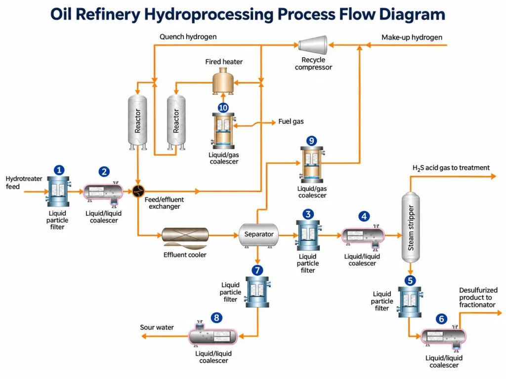
2. Filtration Used in a Refinery: Process-by-Process
A refinery contains several filtration points, each serving a different function.
Typical Refinery Filtration Locations

Conceptual illustration of common filtration locations. Actual refinery process configurations and filtration arrangements vary.
Crude Unit: Crude Oil and Desalter Filtration
Contaminants: Sand, sediment, rust, corrosion debris, and water.
Operational risks: Fouling, erosion, restricted flow, and increased contamination loading in downstream processes.
Recommended solution: Coarse strainers or suitable solids-removal systems may be installed at selected crude-handling points. Desalting uses water washing and electrostatic separation to remove salts and associated contaminants. This process is not equivalent to ordinary cartridge filtration.
Expected benefit: Lower particulate loading and improved protection for downstream equipment.
For crude oil filtration, viscosity deserves particular attention. Heavy crude requires a different hydraulic design from lighter petroleum streams.
Hydrotreater and Hydrocracker: Feed Filtration and Water Removal
Contaminants: Iron sulfide, rust, fine solids, catalyst-related debris, and dispersed water.
Operational risks: Catalyst-bed plugging, increased pressure drop, reduced effective throughput, and unplanned maintenance.
Recommended solution: High-efficiency cartridge filtration ahead of sensitive catalyst systems. Where the process requires it, liquid-liquid coalescers can remove dispersed water from compatible hydrocarbon streams.
Expected benefit: Better catalyst protection, more stable operation, and potentially longer operating cycles.
A hydrotreater feed filter should be selected according to the actual particle-size distribution and allowable pressure drop.
A finer micron rating is not automatically better. Excessively restrictive filtration can create unnecessary pressure loss.
Hydrogen Recycle and Make-Up Gas: Protecting Compressors
Contaminants: Liquid hydrocarbon mist, water droplets, and suspended solids.
Operational risks: Compressor fouling, seal damage, vibration-related concerns, and reduced equipment reliability.
Recommended solution: Appropriate gas-liquid separation equipment, with high-efficiency coalescing elements where fine aerosol removal is required.
Expected benefit: Reduced liquid carryover and improved protection for downstream compression equipment.
Large liquid slugs require suitable bulk separation and protection systems. Fine coalescers should not be treated as substitutes for properly designed knockout drums.
Fuel Gas and Amine Systems
Contaminants: Hydrocarbon aerosols, particulate matter, corrosion products, and entrained amine.
Operational risks: Foaming, absorber instability, downstream contamination, and reduced gas-treatment performance.
Recommended solution: Gas-liquid inlet coalescers, liquid filtration in amine circuits, and appropriately engineered separation stages.
Expected benefit: Lower contamination loading, improved operating stability, and reduced maintenance demand.
Amine-system filtration needs careful attention to chemical compatibility, since the process involves corrosive contaminants and varying operating conditions.
Final Products: Gasoline, Diesel and Jet Fuel Polishing
Contaminants: Rust, tank sediment, dispersed water, and contamination introduced during handling.
Operational risks: Product quality failure, storage problems, customer complaints, and delivery rejection.
Recommended solution: Particulate polishing filters followed by a suitable water-separation system where required.
Expected benefit: Cleaner finished products and improved reliability during transfer, storage, and distribution.
Diesel water removal may use coalescing technology, while aviation-fuel systems require equipment qualified for the applicable fuel and operating conditions.
We do not recommend assuming that a general industrial diesel filter automatically meets aviation fuel requirements.
Catalyst Fines and Slurry Oil Filtration
Contaminants: Fine catalyst particles, coke, and other suspended solids.
Operational risks: Abrasion, downstream fouling, and difficulties processing or upgrading heavy fractions.
Recommended solution: Application-specific high-temperature filtration, backwash systems, or other engineered solids-separation technologies.
Expected benefit: Improved handling of contaminated process streams and reduced downstream solids loading.
Slurry oil conditions can be severe. High temperatures, viscosity, particle concentrations, and operating pressure must be evaluated before selecting filtration equipment.
3. Types of Refinery Filters and How They Work
Different refinery filter technologies serve different contamination-control objectives.
Understanding their mechanisms helps engineers avoid unnecessary cost and incorrect equipment specifications.
Bag Filters
Bag filters capture suspended particles as contaminated liquid passes through filter media held inside a supporting basket.
They are commonly considered for relatively high solids loading, coarse or intermediate filtration, and selected utility or hydrocarbon applications.
Advantages include straightforward element replacement, relatively simple construction, and a broad choice of media.
Limitations include variable fine-particle efficiency and maintenance requirements when bags become heavily loaded.
For critical service, the efficiency claim must be verified under conditions relevant to the application.
Pleated and Depth Cartridge Filters
Pleated cartridges use folded filtration media to provide a large surface area within a compact element.
Depth cartridges capture particles through the thickness of the media rather than relying entirely on surface retention.
Both technologies can provide effective particle removal, but their performance differs according to media design and contaminant characteristics.

Pleated cartridges are often appropriate where controlled removal efficiency and low initial pressure drop are priorities.
Depth filters can be useful where particles vary in size and the medium can retain contaminants throughout its structure.
We assess both initial performance and dirt-holding capacity when comparing cartridge designs.
High-Flow Cartridge Filters
High-flow cartridge filters are designed to process substantial liquid volumes through relatively large elements.
Their major advantage is the possibility of reducing the number of elements required for a given flow rate.
In a large refinery installation, fewer elements may reduce replacement labor and maintenance handling.

However, actual element count depends on fluid viscosity, flow distribution, contaminant loading, and allowable pressure drop.
High-flow design should never be evaluated by flow capacity alone.
Liquid-Liquid Coalescers
A liquid-liquid coalescer separates dispersed droplets of one liquid from another immiscible liquid.
For diesel purification, the objective may be to collect fine water droplets into larger droplets that can separate more easily.
The process normally involves droplet capture, coalescence, and subsequent phase separation.
Coalescers perform best when their media and operating conditions match the particular liquid system.
Stable emulsions, surfactants, and unfavorable interfacial properties can make separation difficult.
Therefore, we recommend examining fluid chemistry before promising water-removal performance.
Liquid-Gas Coalescers
Liquid-gas coalescers capture fine liquid aerosols carried in gas streams.
The media promotes droplet collection and growth, allowing liquid to drain under suitable flow and orientation conditions.
Typical applications include compressor protection, fuel gas treatment, and upstream protection for gas-processing equipment.
For gas coalescers, superficial velocity, aerosol loading, drainage, and pressure drop are critical.
An undersized vessel may create re-entrainment or liquid carryover even when the installed elements have adequate capture efficiency.
Filter Separator Vessels
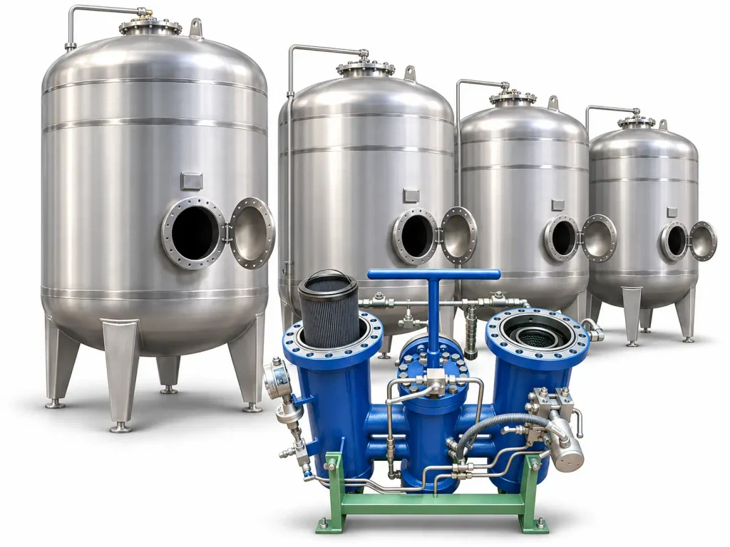
Filter separator vessels combine filtration and liquid separation functions within an engineered pressure vessel.
Depending on the design, the system may use multiple filtration and separation stages.
These vessels are common in applications requiring both particulate removal and liquid separation.
The equipment must be designed for the specified pressure, temperature, fluid chemistry, and applicable mechanical codes.
In aviation fuel service, equipment selection also requires attention to relevant qualification standards.
Self-Cleaning and Automatic Backwash Filters
Automatic backwash filters remove retained solids through a cleaning cycle without routine manual replacement of disposable media.
They can be suitable for streams with significant or continuous particulate loading.
Benefits may include reduced disposable-element consumption and more continuous operation.
However, the system introduces additional valves, controls, cleaning-fluid requirements, and discharge handling.
Automatic cleaning does not guarantee that every contaminant can be removed effectively.
We recommend evaluating particle characteristics and cleaning effectiveness before choosing this technology.
Quick Comparison Table: Refinery Filtration Technologies
| Filter type | Typical filtration role | Suitable media | Replacement / maintenance | Cost consideration |
|---|---|---|---|---|
| Bag filter | Coarse to intermediate solids removal | Compatible industrial liquids | Replace loaded bags | Relatively low initial element cost |
| Pleated cartridge | Fine particulate control | Hydrocarbons and compatible liquids | Replace at specified terminal conditions | Higher efficiency options |
| Depth cartridge | Multi-layer particulate capture | Selected liquids and process streams | Replace when loaded | Media capacity matters |
| High-flow cartridge | High-throughput solids removal | Large-volume liquid streams | Fewer, larger elements may be needed | Potential labor savings |
| Liquid-liquid coalescer | Dispersed liquid removal | Immiscible liquid mixtures | Replace based on performance and loading | Requires upstream contamination control |
| Gas-liquid coalescer | Aerosol removal | Process and fuel gases | Monitor pressure drop and drainage | Vessel sizing is critical |
| Filter separator vessel | Combined solids and liquid separation | Application-specific liquids or gases | Service elements and separation hardware | Higher equipment complexity |
| Automatic backwash filter | Repeated solids removal | Compatible high-solids streams | Cleaning cycles and periodic inspection | Higher capital cost, potentially less consumable waste |
Note: Exact micron ratings, operating limits, and replacement intervals depend on the selected product and application. They cannot be assigned reliably from filter type alone.
4. How to Choose the Right Filter: A Buyer’s and Engineer’s Checklist
Selecting refinery filtration equipment requires more than matching flow rate and micron rating.
At Cofilters, we recommend beginning with the contamination problem and working toward a technical specification.
This approach reduces the risk of selecting equipment that looks suitable on paper but fails under actual operating conditions.
Define the Contaminant and Process Stream
First, identify what must be removed.
Solid particles, free water, emulsified water, and liquid aerosols require different filtration technologies.
The process stream must also be characterized.
Important parameters include operating flow, temperature, pressure, viscosity, density, chemical composition, and expected contaminant concentration.
For example, crude oil filtration at elevated temperatures requires different materials and hydraulic calculations from ambient-temperature diesel polishing.
A filter designed for clean diesel may not tolerate the same conditions as a hot hydrotreater feed stream.
We recommend requesting representative samples and relevant fluid analysis whenever the contamination problem remains unclear.
Select the Right Micron Rating and Efficiency
Micron ratings describe particle size, but they do not always provide enough information to compare filter elements.
A nominal rating generally indicates a stated retention performance under specified conditions. Since manufacturers may use different definitions and test methods, nominal ratings are not automatically comparable.
An absolute rating should be associated with a documented efficiency criterion and relevant test conditions.
One useful indicator is the filtration beta ratio:
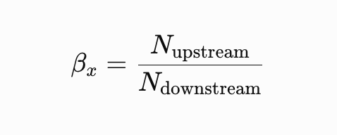
where the particle counts refer to a specified particle-size threshold.
The corresponding efficiency is:
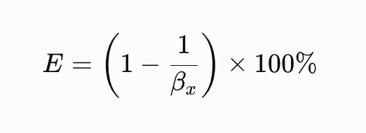
| Beta ratio | Calculated efficiency |
|---|---|
| β = 2 | 50% |
| β = 10 | 90% |
| β = 100 | 99% |
| β = 200 | 99.5% |
| β = 1,000 | 99.9% |
These calculations are mathematically valid when the upstream and downstream counts use the same defined particle threshold.
ISO 16889:2022 establishes a multi-pass testing method for hydraulic fluid power filter elements. Its results should not be presented as automatically transferable to every hydrocarbon filtration application.
We recommend asking suppliers to identify the rating method, test conditions, efficiency threshold, and supporting data.
Match Materials to Operating Conditions
Material compatibility is a fundamental requirement.
A filter element typically includes media, support components, end caps, adhesives or bonding materials, and sealing components.
Each part must tolerate the operating fluid and temperature range.
For refinery applications, material selection may be influenced by sulfur-containing compounds, amines, acidic contaminants, aromatic hydrocarbons, and other chemicals.
The pressure rating of the complete vessel must also be distinguished from the differential-pressure capability of the filter element.
A filter that withstands normal operating pressure may still collapse under excessive differential pressure.
We therefore recommend confirming both structural strength and chemical compatibility before approving a replacement element.
Disposable vs. Regenerable Filtration
Disposable elements provide a practical solution for many relatively low-solids applications.
They can offer predictable replacement procedures and controlled contamination removal.
However, applications with continuous high particulate loading may consume substantial quantities of replacement elements.
Regenerable or automatic backwash systems may reduce consumable demand.
The correct decision depends on solids concentration, required efficiency, cleaning capability, waste handling, and operating costs.
We recommend comparing both options using a defined operating period rather than relying only on initial equipment quotations.
Pre-Filtration to Extend Coalescer Life
One of the most important filtration design decisions is where to place the particulate filter relative to the coalescer.
A coalescer is designed primarily to separate dispersed liquid droplets. Heavy particulate loading can obstruct its media and reduce effective separation performance.
Installing an appropriate particulate pre-filter upstream can protect the coalescer.
Consider a diesel polishing system that receives fuel with both corrosion debris and fine water droplets.

If the fuel enters the coalescer without sufficient pre-filtration, solid contaminants may accumulate within the element.
The result can be rising pressure drop, reduced service life, and additional replacement costs.
A dedicated pre-filter can reduce this loading.
However, pre-filtration cannot eliminate all coalescer problems. Surfactants, stable emulsions, and unfavorable fluid properties may still interfere with separation.
Compatibility with Existing Housings
Many refinery purchasing projects involve replacing existing elements rather than purchasing complete filtration systems.
Compatible replacement filters can potentially reduce capital expenditure and simplify installation.
However, matching the external dimensions does not guarantee functional interchangeability.
Engineers should verify the element length, outside diameter, inside diameter, sealing arrangement, end-cap geometry, flow direction, and mechanical strength.
They must also verify operating performance, not simply physical fit.
Where the original product is part of a qualified system, the proposed replacement must satisfy the applicable approval and qualification requirements.
We recommend requesting a documented compatibility review before changing suppliers.
Refinery Filter Selection Checklist
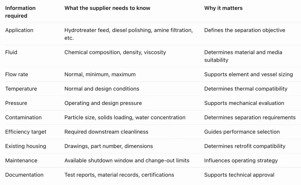
Request a refinery filtration selection review: Submit your operating parameters and existing filter specifications to Cofilters at www.cofilters.com.
5. Common Filtration Problems and Troubleshooting
Even a correctly selected filtration system may experience performance problems when operating conditions change.
A structured troubleshooting approach helps engineers identify the cause without replacing equipment unnecessarily.
Rapid Differential Pressure Rise
Symptoms: The filter differential pressure increases faster than expected. Flow may decline, or elements may require frequent replacement.
Common causes: High solids loading, an unexpected upstream contamination source, increased fluid viscosity, undersized filtration area, or unsuitable media.
Recommended actions: Review differential-pressure trends, check fluid temperature, inspect used elements, and analyze contamination samples.
If solids loading has increased, investigate upstream corrosion, tank sediment, or process changes before selecting a different filter.
Increasing filtration area or improving pre-filtration may help, but the solution should follow a diagnosis.
Coalescer Disarming and Surfactant Issues
Symptoms: Water separation performance declines even though the element may not show an unusually high differential pressure.
Common causes: Surfactants and other surface-active compounds can modify droplet behavior and interfere with effective coalescence.
Recommended actions: Review chemical additives, detergents, and possible process contamination. Examine interfacial properties and conduct representative fluid tests when necessary.
Replacing the coalescer with a finer particulate filter is not a reliable solution to a surface-chemistry problem.
We recommend testing the actual fluid system before changing coalescer media.

Water Carryover in Diesel and Jet Fuel
Symptoms: Water appears downstream of the filtration system, or water content exceeds the specified operating requirement.
Common causes: Excessive water loading, damaged separation elements, incorrect flow, poor drainage, unsuitable media, or emulsion-related problems.
Recommended actions: Check water-drainage systems, differential pressure, element installation, inlet loading, and flow conditions.
For aviation fuel, verification must also cover the applicable qualification and operating requirements.
A general-purpose refinery coalescer should not be assumed to meet EI 1581 requirements.
Compressor Fouling Caused by Liquid and Solid Carryover
Symptoms: Increased compressor maintenance, contaminated downstream equipment, deposits, or abnormal operating trends.
Common causes: Inadequate bulk liquid separation, poor aerosol removal, liquid re-entrainment, or excessive contaminant loading.
Recommended actions: Inspect upstream separators, mist-elimination equipment, coalescer elements, and liquid drains.
If large liquid slugs are present, address the bulk separation problem before attempting to improve fine aerosol filtration.
Premature Filter Failure
Symptoms: Collapsed elements, damaged seals, ruptured media, or leakage.
Common causes: Excessive differential pressure, unsuitable materials, incorrect installation, pressure surges, or chemical attack.
Recommended actions: Confirm the element’s pressure and temperature limits, inspect the sealing arrangement, and compare actual conditions with the approved design envelope.
A damaged filter should not simply be replaced with another element of the same specification until the cause has been identified.
Troubleshooting Reference Table
| Problem | Most useful initial checks | Possible corrective action |
|---|---|---|
| Fast pressure-drop increase | Contamination loading, viscosity, temperature | Improve upstream contamination control or resize |
| Short cartridge life | Solids concentration, media capacity | Review media and filtration area |
| Poor water separation | Water loading, fluid chemistry, flow | Investigate emulsion and coalescer performance |
| Liquid carryover | Drains, vessel velocity, element condition | Correct drainage or separation design |
| Filter collapse | Differential pressure, bypass, element strength | Review mechanical limits and operating controls |
| Downstream solids | Seals, installation, filter efficiency | Correct bypass or retention problems |
6. Filtration in Upstream Oil Production
Although our main focus here is petroleum refining, filtration also plays an important role in upstream oil production.
The two sectors share contamination-control principles, but their operating conditions and treatment objectives differ.
Produced Water Treatment
Produced water may contain dispersed oil, solids, dissolved contaminants, and treatment chemicals.
Separation typically requires multiple stages. Depending on the application, these may include hydrocyclones, flotation, media filtration, and membrane treatment.
The treatment scheme depends on whether the water will be discharged, reused, or reinjected.
Water Injection Filtration
Water injection systems require control of suspended solids to limit plugging and maintain injection performance.
The filtration specification must reflect reservoir and injection-system requirements.
For these applications, particle-size distribution, solids loading, and water chemistry are important selection factors.
Wellhead Filter Separators
Wellhead separators manage multiphase production streams.
Some installations use specialized filtration or coalescing stages for fine contaminants.
However, a filter separator does not replace the primary multiphase separation equipment required for bulk gas, oil, and water handling.
We recommend evaluating upstream applications separately from refinery product filtration, even when similar element technologies are involved.
FAQ
-
How Many Oil Refineries Are There in the United States?
According to the U.S. Energy Information Administration (EIA), the United States had 130 operable petroleum refineries as of January 1, 2026. This figure includes operating and temporarily idle facilities. The total number changes as refineries open, close, restart, or undergo facility conversions.
-
What Is an Oil Refinery and What Does It Do?
An oil refinery is an industrial facility that processes crude oil into usable petroleum products. It uses physical separation, chemical conversion, and treatment processes to produce gasoline, diesel, jet fuel, liquefied petroleum gas, lubricants, and petrochemical feedstocks for transportation, manufacturing, and other industries.
-
What Is Petroleum Refining?
Petroleum refining is the industrial process of converting crude oil into valuable fuels and other petroleum products. It involves three main operations: separating crude oil into fractions, converting heavier hydrocarbons into lighter products, and treating intermediate streams to meet required product specifications.
-
What Is Refined Oil?
Refined oil is petroleum that has undergone processing to separate, convert, or remove unwanted components. Depending on the refining process, the resulting products include gasoline, diesel, kerosene, jet fuel, lubricants, and other hydrocarbons. Refined oil is not a single standardized product.
-
How Does an Oil Refinery Work?
An oil refinery works by separating crude oil into different hydrocarbon fractions through distillation, then converting selected fractions through processes such as cracking and reforming. Additional treatment removes unwanted contaminants and adjusts product properties to meet fuel specifications and commercial requirements.
-
What Is a Refiner?
A refiner is a company or organization that processes crude oil or other hydrocarbon feedstocks into petroleum products. Refiners operate industrial facilities, manage refining processes, and supply products such as gasoline, diesel, jet fuel, and petrochemical feedstocks to commercial markets.